
THE QUESTION
The question I wanted to answer was, “Does making a bow tie (BT) antenna with longer elements improve the VHF response of the antenna?” It is easy to answer this question for a dipole antenna, but the theory for a BT antenna is very different. It states that the frequency response of the antenna is related to the angle between the elements and has nothing to do with the length. So if that is to be believed, then the answer to this question should be, no. On the other hand, I was hoping for some improvement because the antenna would be closer to the best dipole length needed for receiving channel 7. I was able to make the longest set of elements 16″ long for a half-wave BT antenna of 32″ long. This is the dipole antenna length for the frequency of ~ 184.55 MHz, and that’s within the channel 8 bandwidth of 180 to 186 MHz. Channel 7 would be the range 174 – 180 MHz and a dipole for the lowest frequency of 174 MHz would be 33.94″ or ~ 34″ or each half of 17″.Jjust one more inch but the hangers I had weren’t long enough. Still, this should give us some indication of any improvement.
The 8″ version used was that of my “standard” BT antenna. This is the antenna I test all other antennas against. In a previous blog, “The Standard Bow Tie Antenna” I gave the building instructions for this antenna. See Image 1 for the sketch and dimensions.
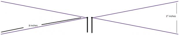
Image 1: The Standard BT Length and Separation
THE ANTENNAS
To test the above question, I cut three sizes of BT elements, (see Image 2) in order to make a single BT antenna for each size. The BT antennas were then made from elements of lengths of 8, 12 and 16 inches with separations of 3, 4.5, and 6 inches so that the inner angle was about 22 degrees for each antenna.
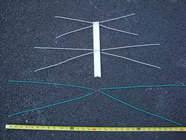
Image 2: Three Sizes for the Simple BT Antenna Elements
Before going into the details of the test data, I’ll describe the location, my test procedure, and my experimental error test.
THE LOCATION
The location was on Mount Airy Ridge in the elementary school’s parking lot, which had a good view of east to Baltimore, a somewhat blocked view south to Washington, D.C., and a clear view west to Frederick, MD.
There was a nice spread of stations and frequencies represented from this location. The channels found were: VHF: 7, 8, 9, 10, 11, 12, 13 and UHF: 15, 18, 21, 23, 24, 27, 28, 29, 33, 34, 35, 36, 38, 39, 40, 41, 42, 46, 47, 48, and 50. A station had to be at least 34 dBuV with the standard BT antenna for it to be used for these comparison tests.
EXPERIMENTAL/MEASUREMENT ERROR
Before readings for the actual comparison tests were done, a subset of channels was tested for the standard antenna ten times so that a crude set of experimental error and repeatability data was collected. The results of this test are seen below and show that the error/repeatability is about +/- 1dBuV and that’s what will be used to see if there really is any difference between the different antennas when tested here for the length, angle, spread, transformer use, and also the comparison between these single BT antennas and the 8″ quad bowtie tests.
Repeatability Measurements
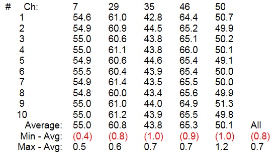
I also tested with and without a transformer. The results of that test will be discussed in a future article. For this length test, I will only use the data from the no transformer tests since this data had a number of advantages. The most important was that the lowest values were noticeably higher without the transformer than with it, and there were no detrimental decreases in any signal level.
THE TESTS/EXPERIMENT
The experimental procedure used was that: all antennas were placed at the same relative height. This was easy to do with the single BT antennas since the same antenna mount was used. See Image 3.
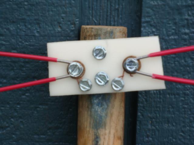
Image 3: The Bow Tie Antenna Mount
When the quad was mounted, it was placed so that the center of that antenna was at the same height as that of the single BT antennas. See Image 4:
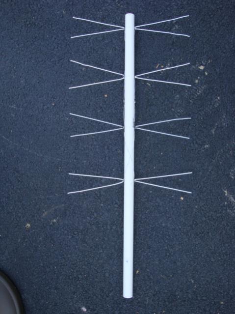
Image 4: The Quad Bow Tie Antenna
The method used for testing all antennas was as reproducible as I could make it. The minimum and maximum signal level positions were found for the channel being tested and then the antenna was rotated so that the test started at the minimum position. The meter reading was reset, and the antenna was then rotated 360 degrees in one direction through both maxima and stopping at the original minimum. Then it was rotated back 360 degrees in the other direction through both maxima again and finally stopping at the original minimum. This insured that the best antenna pointing position was gone through twice and only the maximum value was then recorded. I did my best to rotate the same way for the same length of time but I know there was some variation. The same coax and connectors were used as was the same ferrite clip-on RF choke.
Besides the average gain of the antenna, another quality that may be of interest is the spread of the gain for a given antenna over all the channels tested. If this shrinks and the average gain decreases, it means that the lower gain stations are improving at the expense of the better gain stations. If the spread decreases and the average gain increases, it can mean a few things. The most interesting is that the gain of the lower gain stations is improving while the gain of the higher gain stations is remaining about the same. This would be the best condition we could want in a wide-band antenna.
OBSERVATIONS
Since the signals used are coming from real stations at different locations, different signal paths, different transmitter power levels, etc., there is no way of really knowing, (without more work than I have time to do) the true signal levels for each station and then adjusting the numbers to compensate for the differences, to end up with the real channel gain. That said, comparing the antennas still gives us an idea of which antennas have gain and better spread numbers over the others. What I mean is, even though the signal level for channel 8 was the lowest used for these tests at ~38 dB and the highest was channel 41 at ~75 dB, this difference is probably due to the difference in things such as the distances, trees, the station’s transmitting signal levels, and other things between the station and the antenna, apart from any difference in the antenna’s gain for the difference frequencies. The relative gain of the antennas for those stations might be identical. But, without a standard transmitter to antenna path and signal level, there is no easy way of knowing. What is possible to know, with this testing arrangement, is which antenna is best for what is wanted.
The DATA
Let’s look at the data and see if anything can be figured out from it.
No Transformer
The information that came with the Digiair DTV Spectrum analyzer said that to insure good reception through all kinds of weather conditions, one should have the signal strength at 50 dBuV or above. This means that if there are stations well above that level, some loss of signal due to the change of antenna length can be tolerated, if it helps improve the reception of stations with signal levels below 50 dBuV.
DATA EVALUATION
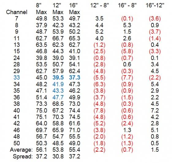
The antenna with the smallest spread was the 12″ BT. It did this by increasing the gain for the four lowest channels of the five VHF stations at the expense of all stations above channel 11, except possibly channel 24 since that was within +- 1dB difference. Both this antenna and the 16″ version improved most of the VHF stations. Compared to the 12″ version, the 16″ BT had lower signal levels for most of the VHF stations and higher signal levels for all other stations.
The BT antenna does not respond to frequencies the way a dipole does. If it had, then the 16″ BT should have had the better gain for the VHF stations than the 12″ BT did, but yet only for channel 8 (which is the channel that the 16″ BT has the best dipole length) was this true.
QUAD
The whole idea of going to a quad element antenna is to increase the gain. The quad BT antenna was tested and compared to the single 8″ and 12″ BT antennas to see if it did, in fact, increase the gain substantially enough to warrant the complexity of building it when compared to the simple single element BT antennas.
Since the 8″ BT is considered a UHF TV antenna, evaluating the 8″ BT against the 8″ quad shows about 3 dB average improvement in gain along with only a 7.9dB increase in max-min deviation. The data shows that almost every UHF channel improved, as one might expect with a quad designed to enhance the UHF channel gain. The spacing between the BT antennas is selected to improve the UHF channel gain without consideration to the VHF stations, but even here it is seen that it is only the lowest two VHF channels which showed any decrease in signal level. From the data below, it looks like there was only one channel substantially below the average gain and it was channel 7 which was about 3 dB lower. There were only two stations at or above/below a change of 1 dB, and if the change range is increased to 1.2 dB, the number of stations with “no essential change” increases to only four channels. Note that even the VHF channels from channel 9 and above also increased and that channels 13 (upper VHF) and 15 (lower UHF) were the channels close to possibly no improvement.
QUAD vs BT DATA
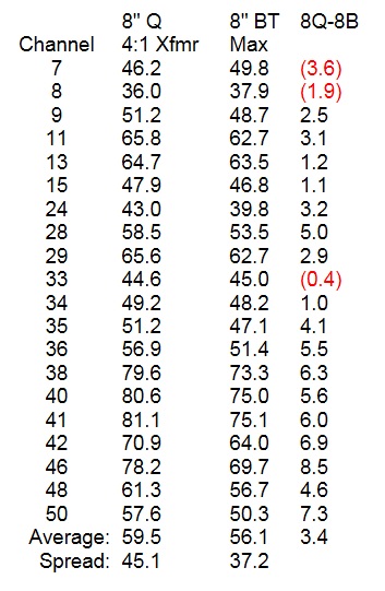
The average signal level for the 8″ quad was only a bit over 3dB better that the simple 8″ BT. It did improve 10 of the UHF channels and the vast majority, nine channels, were in the upper UHF range, (channels 35 through 50). The VHF channels showed substantial losses for only two channels, channels 7 and 8.
COMMENTS
I was figuring that, like a dipole antenna, the simple BT would improve for longer frequencies with a longer antenna. I was hoping that there would be no losses for the UHF frequencies and certainly no substantial losses in the UHF due to the theory saying that the frequency response depended more on the angle between the elements than it did on the length of the elements.
Unfortunately, this was not supported by the data. The 12 and 16 inch versions of the BT did exhibit modest gain over the 8 inch BT in the lower VHF channel sections but there were some substantial loses in the UHF section. There was one UHF station with a signal level below 50 dBuV, and the signal level for this station substantially decreased when either of the longer elements were used.
CONCLUSIONS
It looks like there is no one best antenna for every frequency, even with a BT design. But, it also looks like we can select an antenna which might be a good all-around antenna for our particular situation.
If you live where the UHF stations are far away and some of the VHF stations are closer, either the 8″ BT or 8″ Quad might be the ticket, with the quad being even stronger in the UHF range at the expense of the VHF gain.
On the other hand, if you need to improve the VHF, either the 12″ or 16″ BT might be better. The 16″ BT has improved UHF response over the 12″ so there might be situations where it would be a better selection than the 12″ version. The 12″ looks to be the best for the lower VHF channels while sacrificing the UHF channels but, again, depending on which stations are closer it may be the better choice for your location.
Since these single bay BT antennas are very easy to make, you can test them in your location with the main expense being your time and effort. The materials are probably already in your house or apartment and, even if they are not, the expense is minimal.
So, to answer the question that started this evaluation, we can see that going from an 8″ BT to either of the 12″ or 16″ BTs did improve the VHF signal levels for channels 7, 8, 9, and 11 for the 12″, but only for 8, 9, and 11 for the 16″. The 12″ version was the best of all antennas tested in the VHF range.
So the answer is, yes and no. I was rather surprised with the numbers mostly going down for the VHF stations when testing the 16″ version after seeing an improvement when testing the 12″ version, but that’s why tests are needed.
The next question I wanted to research is, how does using or not using the transformer affect the signal levels?
The question after that I want answered is, does changing the inner angle of the elements improve the signal levels? I’m figuring that the levels will change, but is there an angle that improves everything, or an angle that improves/lowers the signal level range without any substantial losses? Is there an angle to help channels 8, 24, and 33 and not lose too much elsewhere?
After that, I might try two other lengths for the BT: 10 inches to see if it might have the same improvements in the VHF ranges while not suffering some of the substantial loses in the UHF range, and one around 18″ to see if the improvements from 12 to 16 continue and come back to the 8″ levels with improved VHF levels as well.
Look for future columns on these questions.
Until next time, good-watching!