
I said I wasn’t going to give you equations for calculating gain, loss, and Noise Figure/margin but I will explain how I estimate the Noise margin (NM) of the antenna system.
I’ve worked in a number of engineering and physics positions and very early on came up with a quick and dirty way to estimate the things we were interested in. I was able to boil it down to one very simple rule:
Estimating Rule: Always estimate for the worst case.
What do I mean by worst case? Well, perhaps a few examples in the RF world will help with understanding this concept.
Always round to lower the energy transfer: For loss, round the value to a higher loss; for gain, round down to lower gain; when picking a Frequency to use, always use the frequency with the highest loss in the system.
Why I came up with and use the Estimating Rule
I found that, in most cases, this estimating rule leads us to think we have less than is actually true. If we then engineer to this lower estimate, we end up with a benefit at the end of the pipeline. When engineering to manufacture something, this estimating method gives us a very big benefit when compared to estimating to the “best” estimate, which almost always comes out with too positive an outlook, and it is then found that we’ve engineered for a more positive situation than really exists. When this happens, you must spend time trying to figure out a way to improve the situation so that the device can be reliably manufactured. The bottom line is this question, where do you want to be when everything is said and done – with more energy at the output than needed or with less? Personally I’ve always found it a very positive situation to have more or everything than needed to insure an easy-to-manufacture device that is, reliable, repeatable, and reproducible, rather than producing a device that ends up on the border-line of any of these needed manufacturing qualities.
Once there is head room, we can start cutting manufacturing costs to see how it affects “the three Rs” – reliability, repeatability, and reproducibility – of any instrument, be it colorimeter or cell phone.
Example: Quick Calculations
Let’s look at a real-life case and do some quick math to see how this is done and what it tells us.
Caes 3: (Cases 1 and 2 were in my last article.)
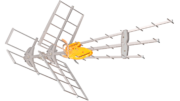
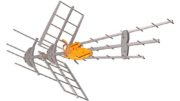
Presently I use two antennas – one for UHF and one for VHF. The signals need to go to two TVs at ~40′ and ~75′. Assuming the worst case for the coax, we have:
- The coax is ~ -6 dB/100′. I used: RF Transmission Line Loss Calculator and RG-11U for 710MHz ~5.824 dB.
- Two short pieces of coax from the antennas to a combiner. Cost: -0.5dB [
- Loss using a combiner, ~ -0.5dB
- A short piece of coax from the combiner to a splitter. Cost: -.5 dB for the 4′ coax, -3.5dB splitter (use -4dB).
- The coax runs: -3 dB for 40′ of coax, and -5 dB for the 75′ of coax.
- Missed losses: -1 dB
Totals:
- 40′ TV: (1) .5 + (2) .5 + (3) .5 + (4) 4.0 + (5) 3 + (6) 1 = -9.5 dB round this down to -10 dB (A higher negative number indicates the signal is going down.)
- 75′ TV: use the above number less (5) for the coax: 7 + (5) 5.0 = -12 dB
With a 12 dB of loss I will only be able to watch signals with a NM of +12 dB or higher since we’re assuming that we need a signal of NM = 0 dB at the TV input, by definition. (This doesn’t count the losses due to a clean roof – no water, snow, ice, etc. on it. Water/rain or snow would cause even higher losses.)
If an amplifier is needed then the insertion loss, (-0.5 dB) and the NF (~ -3.0dB) need to be added to the loss category and, most importantly, this means the signal coming off the antenna must be at least 4 dB above a 0 dB NM so that the amplifier has something to actually amplify besides its own noise.
As it turns out, these antennas (as of November 2012) are able to receive almost all Baltimore TV stations (missing Ch 11 WBAL/NBC) and all Washington stations of interest at both TVs without an amplifier during the winter when there are no leaves on the trees to our south towards Washington. When the leaves come out, even an amplifier doesn’t help, which means the signal levels are below the noise figure plus insertion loss of the best amplifier I have. Or, put another way, the NM at the input of the amplifier is below the needed 4dB to overcome the added amplifier losses. (Below we’ll see that the loss due to the leaves is rather substantial.)
I’ve tested with 5′ of coax from the antenna to a portable TV during the spring with the leaves on the trees and found that there was simply not enough signal for some of the stations (including Ch 26 WETA) for the TV to be able to use. What I don’t know is how far down the signal level is below the insertion losses of the amplifier.
What does this mean? Let’s look at WETA, Channel 26 (real Ch 27) from Washington D.C. This is one of the stations we really want to get. The report for my location, with the antennas up at 20′ says that WETA has a NM of 28.1 dB (For this example we will assume only 27 dB). I used: TV Fool
Understand that these antennas are in the attic, which will cause more loss to the signal, the antenna, if outside, would have ~ 27 dB at the input of the antenna, meaning at the antenna elements. Articles I’ve read say that for roofs like mine, ~ -3 dB of loss can be expected though there are some differences of opinion about the roofing materials being transparent and the rain/water on a roof really causing losses. See:
Attenuation of roofing material – DBSTalk.Com
and
TV Antenna Attic Installation
Since my roof is a shallow slant, this increases the amount of material between the antenna and the signal, so perhaps a -6 dB loss for my situation would be a better estimate. Assuming the worst case that the roof does contribute losses.
The antenna claims to have a gain of ~ 20 dB so I’m going to use only 15 dB of gain. I rounded down to 17 dBi, then I subtracted another 2 dB for dBi vs dBd (dipole). This means that, to start with, there is about 27 + 15 ~ 42 dB of signal at the output of the antenna in the winter, (with no losses for the roof accounted for yet). With all losses from my system (to the closer TV) this goes down to ~ 33 dB. At the further TV it goes down to ~ 30 dB.
Now, subtracting the estimated loss of the roof as well gives:
Antenna Output: 42 – 6 = 36 dB
Closer TV: 36 – 9 = 27 dB
Further TV: 36 – 12 = 24 dB
With these values, I would not expect any losses due to weather being able to reduce the signal and cause any problems, yet I know that this does happen. Again, my antennas are in the attic so that means snow accumulates on the roof in winter and water coats the roof on warmer days. Both will degrade the signal getting to the antenna and if these numbers are to be believed, then the water and snow can add a loss of at least 27 dB!
This also means that, even on dry days in the summer, the leaves between my antenna and the TV station’s antenna cause an even larger loss of at least 36 dB! This is based on the fact that we lose the WETA signal even at the output of the antenna!
If this loss is right on the edge, then moving the antenna outside will give back the 3 – 6 dB of loss the roof contributes and this might just be enough of a signal again. This test has not yet been performed in the summer with this antenna. If, on the other hand, the roof does not contribute any loss it won’t help at all.
Had I done this evaluation prior to putting up my antenna, I would have said that neither weather nor leaves would be able to cause a significant enough degradation of the signal for me to lose these signals in the summer or winter. What could possibly cause a -36 dB loss? Yet these signals are lost due to weather or leaves on the trees. This means that I’ve learned that the possible signal loss due to severe weather, or leaves on a significant number of trees between the receiving antenna and the TV transmitting antenna, can be at least -36 dB.
Until next time, Happy Viewing!
Phil K
All my articles are listed here.