

Let’s go over a few things about dipole antennas that I have picked up while being an amateur radio operator. I will start with what is known and go from there. I will then apply this to over-the-air TV and simple Bow Tie TV antennas.
A word of warning: One of the things I learned when I was a boy was that if you have an idea, give it a try, and see what happens. In school, I learned that sometimes what you don’t know can kill you (think about Madam Curie and radiation). So, please think about what you’re going to try and see if you can find any danger in it. Safety is our #1 concern, so don’t do anything that might jeopardize your safety or that of your family, friends, or neighbors just to try to improve your antenna.
I do all my tests with my feet on the ground and with no overhead power lines anywhere within 50 feet of my location. Please be sure to do the same when you’re testing antennas.
In antenna work, I have tried a number of things, and I will be trying even more. There really isn’t much danger in receiver antenna testing work as long as one follows the above recommendations. There is a little more danger in testing antennas with transmitters but, again, not much, and if you’re testing with low power, then it’s as safe as only testing a receiving antenna. Again, keep your feet on the ground and keep away from power lines. If you’re testing with low power and using battery-operated radios and test equipment, then there isn’t even a concern with the AC lines feeding the equipment.
I am fortunate because I can go to a school parking lot less than 2 miles away on a weekend, and I almost always have a free place with a good view east towards Baltimore, west towards Frederick, MD, and a fairly good view south towards Washington D.C. This gives me a very good range of TV channels (read frequencies) for testing out antennas. The only disadvantage of this arrangement is that I have to wait for a free weekend day and for the weather to cooperate. This combination doesn’t come around nearly as often as I would like.
Presently I have a number of ideas I will eventually get around to testing and writing about. With my acquisition of the Digiair TV frequency analyzer, my ability to test has been greatly expanded. This instrument is much more robust, meaning it can display a number of different parameters such as analog signal level, Bit Error Rate (BER), and Modulation Error Ratio (MER) through the maps of the constellation points. It is much easier to use, more reliable, and more repeatable than anything I have had previously. For anyone still doing TV antenna installation work, this instrument would be of great help. It would perhaps be more than needed in some easy installations, but indispensable in more difficult ones. You can walk around a yard with a simple antenna and watch the signal increase and decrease while you’re moving around. If you do this on a roof, one person can move and hold the antenna while another person watches the display.
If you are unfamiliar with BER, see: https://en.wikipedia.org/wiki/Bit_error_rate and for MER see: https://en.wikipedia.org/wiki/Modulation_error_ratio. These are only two of many other links which will help explain these.
Last, here is a pair of pdfs on Introduction to Digital Terrestrial TV: http://www.digitaltv.gov.hk/consumer/pdf/DTT-PPT.pdf about 1.25 MB and one on Understanding Digital TV: http://www.kte.hu/upload/publikaciok/understanding_digital_tv.pdf at about 3.6 MB. The one titled “An Introduction to Digital Terrestrial TV” is not really worth reading unless you know nothing about DTV. It is the sales pitch as to why we’re moving to DTV, these were made in Hong Kong but they apply for all of us.
“DIGITAL – This measures the power of the complete channel (Average Channel Power), calculating the total power of each carrier (power, not voltage). The unit should be, logically, the milliWatt, or rather dBm (0 dBm = 1 milliwatt), but if you still use dBµV for convenience, (the) ideal value (of) 50 dBµV (should be used).”
“Determining the MER of a digital signal is a critical part of determining how much margin the system has before failure. Unlike analog systems where you can see degradations in Carrier to Noise performance, a poor MER is not noticeable on the picture right up to the point of system failure.” From the slide presentation at: authorSTREAM – Modulation Error Ratio and Signal-to-Noise Ratio Demystified By ABHI ELECTRONICS * Digital Measurement_MER http://www.authorstream.com/Presentation/abhisheksingh0411-1098955-digital-measurement-mer/
Using the Digiair, I can already see the differences in the TV reception at my home and various antennas on a day-to-day basis with cold hard signal levels, BERs, and MERs. While I don’t know exactly what is causing most of these daily differences, it is now very easy to see these differences.
So, let’s start talking antennas on an easy-to-understand idea level.
In one of my previous blog articles, I talked about my understanding of baluns, chokes, and impedance transformers, when to use them and when not. That particular blog has been viewed more than 270 times so I know many of you have some interest in the topic. This blog is a compliment to that article to give us a starting point when talking and thinking about antennas.
From ham antenna books I’ve read, it is known that a dipole antenna (also known as a half-wave dipole), when built to the correct length for any particular frequency, has an impedance of about 73 Ohms. A folded dipole has an impedance of 300 Ohms for the same situation. All of these are for free space antennas. Things change the closer they are to objects or the ground if the antenna is in the clear, at least one-half-wavelength above ground and away from objects, then these numbers should apply. By the way, one-half wavelength of the longest VHF TV channel frequency 82 MHz for channel 6 and 174 MHz for channel 7 is about 1.83m or 6.00ft, 72″ for 82 MHz and 0.86m or 2.83ft, 34″ for channel 7 at 174 MHz. In my area, channel 7, 174 MHz, is the lowest VHF channel being used, but I think I’ve read that elsewhere, channel 6 is still in use. As far as I know, the FCC has allowed stations to return to the lower VHF frequencies but most have not done so because the higher frequencies are better suited for DTV.
For more about dipole antennas see: https://en.wikipedia.org/wiki/Dipole_antenna and http://www.techopedia.com/definition/5053/dipole-antenna
For TV work, the basic half-wave dipole works out well since the TV input is 75 Ohms, so we could build dipoles for the center of the frequency bandwidth of any channel and have a basic antenna. While the half-wave dipole uses the length of the antenna to match a particular frequency, the bow tie antenna uses the outside angle between the elements as the determining factor for the frequency response of the antenna. The theory is based on an infinitely long antenna so that the length does not have any influence on the frequency response. On the other hand, there are two things I’ve noticed: The first is that we are stuck in the real world and not in the theory world where an infinitely long antenna is possible. The second is that the angle used in the article is not the angle commonly used by manufacturers of the bow tie, or antennas based on the bow tie antenna.
For now, I will stick with the way most people are building it and not with the article. For the 8″ version of the bow tie, the separation of the ends of the bow tie is usually 3″. This translates to an angle of 158.4 degrees (the cosecant of 1.5/8). You can try: http://www.1728.org/trig4.htm – The article used an inside angle of 50 degrees, which for an 8″ BT would mean a separation of about 6.75″ or 6 3/4 inches.
WARNING: Never trust a trig calculator that violates the basic relationship between the sides of a right triangle. The relationship, as I’m sure you all remember, is that the hypotenuse (H) squared is equal to side A squared plus side B squared or as an equation: H^2 = A^2 + B^2. This means that the hypotenuse is ALWAYS the longest side! If ever a calculator tells you differently, you have either made a mistake entering the known data or the calculator is wrong. Check your work, and try again.
Another calculator that actually draws the triangle for you on the screen and you can then download is at: http://www.mathworksheetsgo.com/trigonometry-calculators/right-triangle-calculator-online.php
This is the calculator that has problems when entering ONLY the hypotenuse, side AC, and angle A. When I entered 8 for side AC and 25 degrees for angle A, it calculated the other sides as AB: 8.8 and BC: 18.9 which clearly violates the right triangle sides relationship. It’s saying that both sides are longer than the hypotenuse! On the other hand, if I enter AC = 8 and BC = 3.3, which is close to getting angle to 25 deg., it gives angle A as 24.4. With a little work I found that the separation, side BC for 25 degrees, was 3.375 inches, which means the bow tie separation is 6.75″ for an 8″ length on the bow tie element.
Question: Which is better for the 8″ bow tie: a separation of 3″ or one of 6.5″?
Only a test will tell for sure what changes take place and if one is better than the other. This is an easy enough test to make, so it’s in my log book to be done.
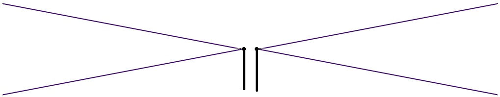
Bow Tie of 8″ and 3″:
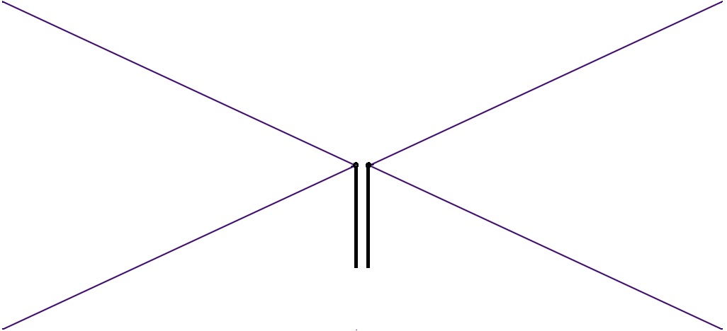
Bow Tie of 8″ and 6.5″:
Let’s pick up where we left off with antenna master Phil Karras!
I now have two questions to answer: (1) How does the length of the BT elements affect the frequency response of a BT antenna? And (2), how does the separation of the ends of the BT elements effect the frequency response of the BT antenna?
In my next installment, I will first try to answer the question, “How does changing the length of the bow tie element affect the frequency response? Does it improve the VHF response of the antenna?” The lengths I’ll use will be 8, 12, and 16″ for antennas of 16, 24, and 32″ The 32″ is as close as I could get to the 34″ for a dipole length for channel 7’s 174 MHz bottom frequency, with the hangers I had available
After I try tests to answer these two questions, I’ll do a more complete test of using or not using a balun for the bow tie and multiple bow tie antennas. Which is better: to use or not to use it?
Until next time, happy viewing!

Be the first to comment on "Simple Dipole and Bow Tie Antennas"