
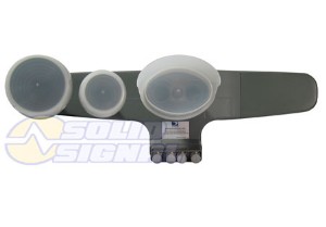
Signal Group Forum User VOS is known throughout the blogosphere for his insights on RF Engineering. We’re extremely lucky to have his analysis of two DIRECTV LNBs.
I’m happy to have an AIM meter for a little while for some tests. I decided to test two LNBs to see the difference.
| WNC | Calamp | change | |
| 99-1 | -30.4 | -27.0 | 3.4 |
| 99-2 | -24.3 | -31.2 | -6.9 |
| 99-3 | -30.3 | -26.4 | 3.9 |
| 99-4 | -23.5 | -30.2 | -6.7 |
| 103a-9 | -20.4 | -32.5 | -12.1 |
| -10 | -26.5 | -31.4 | -4.9 |
| -11 | -19.3 | -30.3 | -11 |
| -12 | -25.9 | -30.5 | -4.6 |
| 103b-1 | -21.9 | -31.7 | -9.8 |
| -2 | -26.7 | -29.7 | -3 |
| -3 | -21.9 | -31.1 | -9.2 |
| -4 | -27.1 | -29.3 | -2.2 |
| offset | 3+ MHz | 1 or less |
Now if this was merely the power output, it would be easy, but when the LO offset is three times more, this suggests the LNB Ka LO is working harder to stay locked.
hummmm the more you get to see the more you can’t make up your mind
went with the higher output over the less LO offset.
Should I have been in a colder climate, I might have gone the other way.
LO drift would be more concern in cold weather, or has in environmental testing.
I don’t know the lock range of the LOs, but would expect a delta of 1 MHz to be acceptable.
If you look at the legacy & SWiM system losses and power levels, you might see that they’re designed [or looks to be] for around a 30 dB range for rainfade.
When the storm gets into the 40 dB attenuation, the system quits.
Some testing has shown the LNBs lose lock at -38/-39 dBm output.
DirecTV tweaks the beam patterns from higher power where there is more rain.
I’m sure not in the stronger beam patterns, so I expect my measurements to be on the lower end.
The -20 dBm range looks like it would only give me about a 15-20 dB range before rainfade.
The LNB that is in the -30 dBm range, looks to have reduced this down to 10 dB or less.
I wish I had more than the 2 legacy LNBs.
The minimum signal before loss of signal has been tested by others, and I got the same results here.
I know SS@SolidSignal has tested his LNB and while there was more coax in use, his numbers were in the -30 dBm range too.
I’d love to have a dozen samples from each of the three suppliers [Aspen/WNC/Calamp] and runs tests to see what the variations are.
I knew going in that the WNC has been known to have more output from installer’s posts, who get to see these everyday.
One of the problems is even the new super duper DirecTV AIM [which I used for these tests] doesn’t lend its guided setup steps to even look at these results.
I needed to run through the options in the meter and then manually select my own tests to get these measurements.
OK, I have to admit I may have some contempt of the idea of putting “all the smarts” into a meter and not empowering the person using it.
I’m so old school that they almost started with teaching us how to mine copper to make wire, how to make every component, and how they all go together.
To test something, you needed to know how the test equipment worked and how it can affect for results.
In today’s world this is Very Old School.
So how good is the IV test in the AIM one might ask?
I connected the AIM to a legacy port off my -16, which has about 17 dB loss from the input.
The IV test failed.
Looking into the details showed the only failure was low power.
99 even passed, but all the others failed.
So what is the power on the lowest even/odd tps?
99-1 = -43.6 dBm
99-2 = -41.5 dBm [this one passed]
101-1 = -44.1 dBm
101-2 = -46.0 dBm
103a-9 = -46 dBm
103a-10 = -45 dBm
103b-1 = -41.9 dBm [doesn’t look like it was part of the IV test]
103b-2 = -40.9 dBm [doesn’t look like it was part of the IV test]
110-10 = -46 dBm
119- 23 = -46.6 dBm
119-22 = -47.4 dBm
Maybe these aren’t the TPs used for the IV, but they’re the first ones in the menu for each SAT.
The alignment menu uses tp 25 off of 101.
If 99 even/odd readings do hold true, then the IV passes with a signal level just a couple of dB below where the LNB breaks lock.
My next round is going to be attenuating the LNB input which is the rainfade condition.
I have to say my next tests are quite surprising.
I masked off the aperture of the main LNB and also used a soaked towel to reduce the LNB input power.
The IV test failed the SNR reading, in both cases.
It was also surprising at how little of the reflector needed to be covered with the wet towel too before the 101 SAT would fail. 99 & 103a [which is what’s tested in the VI] would pass when the 101 wouldn’t].
Power levels weren’t that changed, but the SNR sure takes a hit.
My current gating item to pass the IV test is the 101 odd TP SNR where TP 15 fails @ 10.4 dB, and passes @ 10.7 dB.
103a passes with a 7.9 dB SNR.
99 I haven’t picked apart yet, but fails much earlier than 103. but not as much as 101 odd.
I think I need to completely re-think how to simulate rainfade.
I’ve been “clipping off” an edge of either the aperture of the LNB or the top edge of the reflector.
The LNB can get covered just shy of 50% and keep locked.
The reflector gets clipped 3 inches and the SNR goes to hell.
The SNR degrading didn’t matter where my damp cloth was placed. It was the same if positioned in the center or on the edge.
“Oh BTW”: the -16 pulls its guide data off the 101 even TPs because I got the no guide data update for one hour message, while I’ve been playing.
So I’m now just stumped. The slightest damp cloth will barely pass VI due to the SNR, and doubling up this handkerchief causes a failure.
It’s good that the IV test threshold is so high, as the receivers work down to 6-8 dB SNR, which is well below the AIM limit, but I can’t simulate rainfade, without something else.
“Something else” turned out to be 100 grit sandpaper. 40 sheets in fact, which is a good 3/4″ thick, and would attenuate the output power and the SNR of the 101 signals equally.
Now to try to answer why go through all of this:
1) I’ve spent many years testing/building state of the art equipment that does what these cheap LNBs do, but cost $100,000+ [with “just a few” more features].
2) to characterize/define the LNB output to know what determines a good setup.
My original pretext was the LNB was a block converter with a couple of amps.
Output level would relate to loss/gain of the stages and input level.
My sandpaper and wet cloth aren’t calibrated to know how much attenuation I was adding, which I thought the power level would reflect, but it didn’t in the testing.
SNR & output power changed at the same rate, making output power as sign of how much “rainfade” resistance meaningless.
Testing has shown the LNB will break lock with levels below -39 dBm and as high as -33 dBm output.
The IV test fails output power in the -40 dBm and less range.
The SNR test looks to be a much higher priority.
The paradigm shift here for an LNB is:
- SNR
- LO offset
- output level
Where previously it was:
- output power
- LO offset
- SNR
While I’m waiting for the meter to recharge, which it needed right after I went to test the other LNB for it’s SNR, The first LNB was measured for its output while sitting on my dining table.
99
odd -37 dBm
even -34 dBm
101
odd -38 dBm
even -40 dBm
103a
odd -27 dBm
even -30 dBm
103b
odd -34 dBm
even -38 dBm.
This is with the LNB pointed straight up at my ceiling, so the odds of it receiving a SAT signal are, well less than zero.
| WNC dBm | SNR dB | Calamp | gain diff dB | SNR diff dB | ||
| 99-1 | -30.4 | 11.0 | -27.0 | 9.1 | +3.4 | -1.9 |
| -2 | -24.3 | 12 | -31.2 | 9.9 | -6.9 | -2.1 |
| -3 | -30.3 | 11 | -26.4 | 9.2 | +3.9 | -1.8 |
| -4 | -23.5 | 11.7 | -30.2 | 10.2 | -6.7 | -1.5 |
| 101-1 | 12.8 | 12.2 | -0.6 | |||
| -2 | 13 | 12.2 | -0.8 | |||
| -3 | 12.3 | 11.8 | -0.5 | |||
| -4 | 14.6 | 14.1 | -0.5 | |||
| 103a-9 | -20.4 | 11.1 | -32.5 | 9.6 | -12.1 | -1.5 |
| -10 | -26.5 | 10.9 | -31.4 | 10.3 | -4.9 | -0.6 |
| -11 | -19.3 | 12.3 | -30.3 | 10.7 | -11 | -1.6 |
| -12 | -25.9 | 11.5 | -30.5 | 11 | -4.6 | -0.5 |
| 103b-1 | -21.9 | 11.8 | -31.7 | 11.3 | -9.8 | -0.5 |
| -2 | -26.7 | 12.3 | -29.7 | 9.9 | -3 | -2.4 |
| -3 | -21.9 | 11.5 | -31.1 | 10.6 | -9.2 | -0.9 |
| -4 | -27.1 | 11.3 | -29.3 | 10 | -2.2 | -1.3 |
Since the output power variations between these two LNBs varies much more than the SNR, I’m going to speculate that:
While the final output power does effect how long the coax runs can be, rainfade resistance is going to come from the first amp’s gain.
With the output signals so high without an input signal, it points to the LNB not having a filter after the mixer stage:
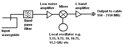
When you build a better mouse trap, you filter the mixer/LO noise out more.
The cliff notes version:
When a tech comes out, make him look at the SNR or CNR value and maximize this for the best alignment/performance.
Just about everything else is meaningless.
If you’re in cold weather areas, might want the LO offset to be low also as in cold temps, it might break lock and drift to an adjacent channel.
Since a SWiM will add gain to inputs as low as -45 dBm, “It doesn’t really matter” what the output is as long as it’s within range.
Adding amps will only help long coax runs.
Be the first to comment on "A technical guide to the LNB"