
Insertion loss is another one of those terms you really want to understand, and then you go to some other web site and they hit you with some totally wigged out formula like:

which isn’t going to help you at all.
Plain and simple, one thing you can always say about electronics is “There ain’t no such thing as a free lunch.” When you put something in line, or when you split a signal, or even when you add an amplifier, you always lose something. No matter how clean the connection is, no matter how well it’s put together, adding something in line always means you end up with a weaker signal. Period. Oh, you can amplify that weaker signal to compensate, but it’s always, 100% of the time, weaker.
How much weaker?
Well you could look at that formula, but in reality there are two ways to get the answer you seek: the manufacturer’s specs and simple math. Almost every device will list insertion loss and what you are looking for is a low number. Ideally, a passive device without a lot of circuitry would have a 1dB or less insertion loss, and then you have to add in the loss from the connector which is usually about 1dB.
dBs? What’s that?
dB, or decibels, is a good way to measure signal and power because it helps keep the numbers relatively consistent even when they change massively. It’s possible for a signal to degrade a lot before it is lost, so you tend to get very small fractions when you use percentages. 1dB loss means you lose about 20% of what you had, while 15dB loss means you lose about 97% of what you had.
The nice thing about dB is that you can simply add them to get total loss. In a case like above, 1+15 = 16dB loss which is a lot easier than trying to combine 20% loss and 97% loss to get 98.5% loss (which doesn’t seem right but it is.)
Powered devices and complex systems have much higher insertion losses because every component has its own insertion loss and it all adds up. It’s not uncommon to see insertion losses for an amplifier at about 10dB, and this is part of the calculation of what you’re getting. A 20dB amplifier will first overcome its own insertion loss and then add 20dB.
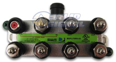
The other thing you can do is simply add. Splitters have very predictable insertion losses. The splitter itself usually has an insertion loss of about 1.5dB, and then you lose strength when you split the line.
-
a 2-way splitter puts 50% of the signal on each leg. 50% = 3dB loss.
-
A 4-way splitter puts 25% of the signal on each leg. 25% = 6dB loss.
-
An 8-way splitter puts 12.5% of the signal on each leg. 12.5% = 12dB loss.
So, take the loss from splitting and add the 1.5 dB average from the splitter and you have the total insertion loss. So, if you don’t know for sure what the insertion loss of a 4-way splitter is, assume it’s 6 + 1.5 = 7.5dB. Also, keep in mind that you should round up a bit. The actual mechanical parts of a splitter add a fraction of a dB to the loss equation, as to do the connectors used on the ends of the cable.
Why do you care?
Because you need to plan for loss when you’re moving signal around the house. The more splitters you add, the more you lose. The more cable you run, the more you lose. You can add amplifiers but they create loss first. At some point the signal becomes too weak to use. By knowing about insertion loss, you can help avoid this.
This article is sponsored by SolidSignal.com. Shop at Solid Signal for everything you need to live your best digital life.

Be the first to comment on "What is “insertion loss?”"