
Revised and Updated!
You’ve done everything you can... and you’re still having problems with your DIRECTV whole-home system. You’re thinking of giving up… all you want to do is watch TV!! And then the tinkerer in you takes over and you become obsessed with getting it right.
Does this sound like you? If so, read on… there are some strategies for knowing what’s really going on with your DIRECTV system and some tools and guidelines you can use to make your system the best it can be… and know when you have a problem that needs fixing.
This document is available in PDF format! Click here to download!
Step 1: Identify the problem… and decide if there is a problem.
When it comes to DIRECTV whole-home, that means knowing exactly what happens in different rooms. Here are some examples of the kinds of whole-home problems you might encounter. Remember to try the easy solutions first… they will save you a lot of time.
The easiest possible step is to reboot every receiver, one by one. Start by unplugging the power inserter to your SWM for a count of 15, then reboot every DVR one at a time and then every receiver one at a time. This can work wonders. While problems with your wiring aren’t likely to be solved with a reboot, it is an easy diagnostic tool that should be tried before you attempt rewiring or reconfiguring your system. Power down every receiver and accessory in the system, then power everything up in the following order:
- Power up the SWiM
- Power up the DECA Broadband (Cinema Connection Kit)
- Power up each DVR, one at a time, and waiting until it finishes, before moving to the next.
- Power up each receiver and RVU client.
If that doesn’t work… read on for a list of common problems and tips to fix them.
Can’t see all the DVRs in your home.
Sometimes, this is simply a matter of turning on sharing on the DVRs you can’t see. Go to a DVR that can’t be seen and, using your remote, follow these steps:
- Press {MENU}
- Arrow down to “Settings & Help,” Press {SELECT}
- Confirm that “Settings” is highlighted, Press {SELECT}
- Arrow down to “Whole-Home,” Press {SELECT}
- Confirm that “Share Playlist” is highlighted, Press {SELECT}
- Make sure “Share Playlist:” is set to “Yes.” If not, Press {SELECT}
If some receivers can see a DVR but others can’t, this becomes a little more difficult. Make a note of which receivers can see which DVRs and which can’t. If you were able to see a DVR before but you can’t now, make a note of that as well.
You push a button (like Fast Forward) and nothing happens, or something happens very slowly.
Sometimes this is due to weak batteries in the remote. Try another remote, or change the batteries. If you are sure you have fresh batteries, take a look at the DIRECTV logo on the receiver. Does it flash instantly when you press the remote button? If it flashes instantly but nothing happens, that can be a sign of cabling issues. However it can also be a sign of other things.
Fluorescent lights or even the backlight from the TV can cause interference. Try moving the receiver as far as possible from the TV and turning off all the lights. If that makes a difference, slowly move the receiver closer to the TV, or turn on one light at a time to find out where the interference is coming from. If the problem is the TV, a sheet of aluminum foil over the receiver can block this interference. Turning the brightness on the TV down just a little can also help.
It’s also normal to expect that performance from Fast-Forward and Rewind is a little slower using whole-home than it is while watching a program that’s stored on the box you’re in front of. It’s not normal for it to take more than a few seconds to respond.
Error messages pop up, or programs freeze for a second or more while they’re playing.
The whole point of an error message is to help you figure out what’s really going on. Take a look here for a list of error messages and what they mean.
The most common messages you’ll find while using whole-home are 771, 771a, 771b, 775, and 776. These messages will generally appear during live TV but can indicate a problem with your whole-home system. These errors have very specific meanings and often times boil down to wiring issues that you will have to find and fix. If these messages come up on occasion, check to make sure that all the connections in your home are nice and tight. A loose connecction can be hard to spot and can cause huge problems.
If you see freezing on the screen, go back to the DVR and see if the program freezes in the same place if you look at it on another TV. Sometimes this can be a signal issue far beyond your control.
Programs can’t be played on a receiver even though they show up on the playlist.
Sometimes this is caused by someone watching something from the DVR you want to use. HR24 DVRs (and earlier) can only send one whole-home stream at a time. If someone else is watching any program from that DVR you can’t use it. HR34 DVRs can send three streams at a time. in this case you will see a red circle with a white dash next to the program.
Another problem can be caused by HDCP, the content protection in HDMI cables. If you get the message “This program cannot be played on this receiver” it may be that you are using an older TV or have a cable problem. Try switching to component, or swapping out the HDMI cable, and see if that fixes things.
Still having problems?
Make a list of everything that’s happening. Keep it detailed, such as “Can’t play programs from the living room DVR while in the guest room.” It’s time for some detective work.
Before going further: The System Tests
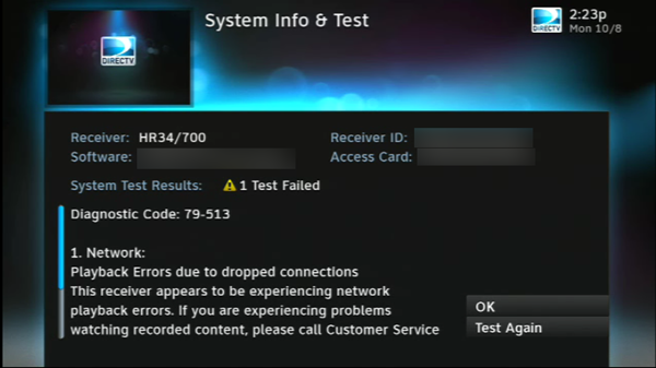
DIRECTV receivers have two built in system tests that are very powerful. The first test screen can be found by pressing-and-holding {INFO} using the white DIRECTV remote. Running a system test from here checks everything about your system. If you get an error message here, use this guide to decode it. This may point you toward a problem you didn’t realize you had. One specific error to look for is Error 46 which indicates reduced network performance. It will be followed by the MAC address of the problem receiver, which you will need later. Another common error is Error 79 which indicates dropped network connections. (Note: Error 79 is commonly seen on Genie HD DVRs where it occurs every time the Genie Client is disconnected. This is normal and can be ignored.)
If you want to do some more advanced testing of the receiver, reboot it and press {SELECT} when you see “Running receiver self-check.” This will take you to a very advanced test menu that will let you test almost every aspect of the receiver and give you at least a pass/fail. This test will also give you the power to erase your hard drive, so be careful.
There are several hard drive tests that can be run that take close to a day to complete. Hard drive errors are rare because the DVRs self-repair but they do happen.
Step 2: Detailed network map
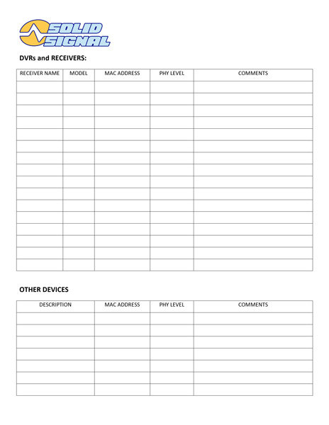
Start with walking around and listing all your receivers and DVRs. For “Receiver Name” put a name that makes sense to you; the room it’s in, or a family member who uses it most. It’s important to list the model because there are some troubleshooting steps that depend on the model you’re using. For now, leave all the other boxes blank… you’ll use them later.
Once you’ve done that, look for any other devices that use coax networking. These would be DECAs that connect to a switch for Blu-ray disc players or smart TVs, plus the DECA Broadband (Cinema Connection Kit) you use to connect to the router. It’s not really necessary to list the SWiM.
Also, draw a diagram of your whole system. Include the SWiM, every receiver, every device, and if possible the cable length between devices. The cable length doesn’t have to be exact, a good estimate is better than nothing.
Step 3: Determining which device is which.
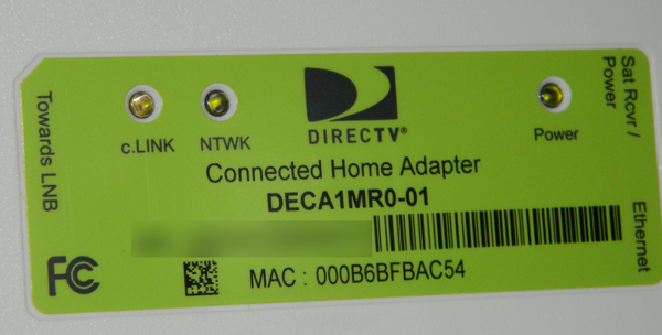
This is a DECA. DECAs and Cinema Connection Kits have the MAC address printed on them. Make a note of the address of every DECA, and write it down next to the receiver or device it’s connected to. Usually all you have to do is write the last 6 or 7 numbers, that should be enough to identify it. Your DECAs may look different — they may be black — but they will still have a MAC address label.
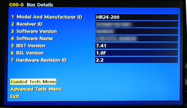
If your home theater consists only of older receivers with DECAs installed, you can skip the next step. Since HR24, H24, H25, and Genie receivers have internal networking, there’s a hidden menu that will allow you to see the MAC address of every connected device.
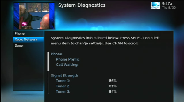
Go to the front panel of the receiver and press {GUIDE} and the right arrow at the same time. This will take some practice to get right. When you do, you’ll see a hidden test menu that looks like the image above. Arrow down to “Coax Network” and press {SELECT}. You can do this part from the remote.
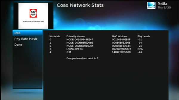
This is a basic DIRECTV setup with 5 devices. Remember, only 16 devices can be on the same coax network. For now you are only interested in MAC addresses. If you see a Friendly Name listed, you will know which MAC address is associated with that device. More often, you will see a name starting with “NODE-.”
In the diagram above, Node #3 has a Phy Levels of “N/A.” The device that shows “N/A” is the device you are testing from, and that’s how you know its MAC address. You may need to run this test on every Genie, HR24, H24, or H25 to find their MAC addresses.
Finding the problem using the hidden menu
This screen tells you a lot about your coax network. Start by looking at the dropped session count. On HR24s this should be zero. If it’s higher than that, and you haven’t disconnected anything in the last 5 days, there may be a loose or broken cable. This test was run from an Genie, which will generate a “dropped session” error any time you turn off a client, so ignore the dropped session count if you run it from an Genie.
Next, look at that Phy Levels listing. What it’s really telling you is the signal strength between any two devices. Look for any number that’s over -45. (In other words, look for -46, -58, -62, something like that.) If you see a number that’s higher than -45 it means that there will be a problem with your coax network. The MAC address list you made will tell you which receiver or device has the problem.
These numbers are the test results for this receiver only. In other words, looking at the sample screen above, from node 3 to node 0 has a -31. It doesn’t tell you what the communication between node 1 and node 2 is… only between node 3 and all the other nodes.
If you wish, you can go from receiver to receiver and check, although there is a simpler way.
The Phy Rate Mesh Test
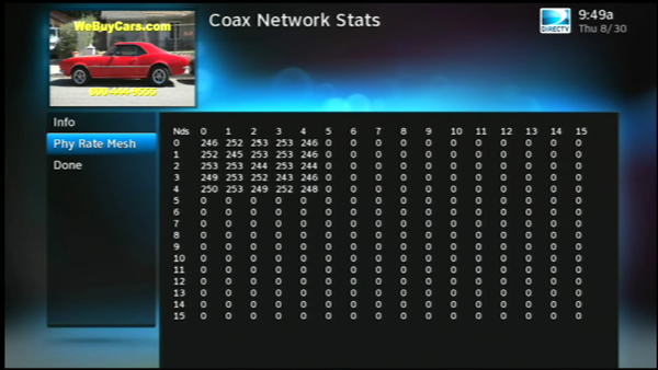
This is the Phy Rate Mesh test. It will test up to 16 devices (remember you can’t have more than 16 devices on a coax network) and how they communicate with each other. Let’s ignore all the zeros (they correspond to devices that aren’t connected) and look closer.
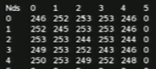
This test returns a number that describes how well information can get from point to point. Every device sends information out and waits for it to come back. Then it gives a grade (255 is best) in this grid. Higher numbers are better. For example, the quality of communication from node 1 to node 3 is 253. The number generated between any node and itself is a sign of phase matching. It’s not a path that is used, so it should be dismissed.
Anything over 240 in this grid means you’re just fine. Anything under 240 means you may have a problem. Numbers in the 230s aren’t necessarily cause for concern if you’re not having performance problems. Anything under 220 will trigger an error.
Typical scenarios and what they mean
All the numbers in the Phy Rate Mesh menu are under 240.
Only one receiver has bad numbers in the Info menu.
Everything works fine but I still have bad numbers in the Info and Phy Rate Mesh tests.
All the numbers look good but I’m still having problems.
Identifying the goal
It’s important to pay attention to both the Phy Levels listing and the mesh test in order to understand the whole picture. Even a loss of less than 45dB can cause a problem, because noise on the line is also a factor. In rare cases the network signal itself, as it travels through more than one path, and a secondary path can be seen as noise too.
Once the problem is identified, the first order of business should be addressing problematic Phy Levels. Unless your Phy Levels are better than -45 (in other words, they need to be -25, -35, etc.) the mesh test is of no concern. Generally this can be addressed through wiring, either improving the quality of the connections or shortening the run lengths. Correct issues with Phy Levels and your mesh numbers should see corresponding improvement.
If mesh levels are still under the recommended numbers even though your Phy Levels are healthy, this can be a sign of noise in the line, RF interference, the wrong splitter being used, or other issues.
Common solutions
Eliminate RF interference
Many intermittent problems are caused by stray RF signals. Your equipment should always be plugged into quality surge protectors to eliminate noisy electrical lines. However, there are other causes of RF interference that often go unnoticed. For example, fluorescent lights can cause RF interference, even the compact ones. Does everything work fine with all the lights off but not with the lights on? RF interference could be to blame. The fluorescent backlight in your television could even be a source of stray signals. Turning the brightness down can solve problems like poor remote performance.
Because satellite cable is shielded, it shouldn’t be affected by RF interference, but remember that it just takes moments to rule out the easy solutions.
Remove unneeded splitters, or move to smaller splitters.
While you may have put in two eight-way splitters thinking you’d need them, you may have consolidated to the point where you only need a 4-way or even a 2-way splitter. Newer multi-tuner DVRs reduce the amount of wiring you need by eliminating the need to have 3 DVRs in order to record 5 programs. Removing an 8-way splitter can save you 12db of loss and that can make the difference.
Remove unneeded lines.
If you originally wired two lines to each room with a DVR, chances are you’re only using one of those lines now. Rather than keeping one as a spare, disconnect it completely. This may increase the integrity of your wiring overall, and may let you move to a smaller splitter.
Terminate, terminate, terminate!
Think of an open coaxial connection as a water spigot that runs constantly. It’s not too different, actually. Pick up a bag of terminators and make sure that every line that you’re not using is terminated. This includes the “SIGNAL TO IRD” connection from your power inserter if you aren’t using it. Every unused port on every splitter (and there shouldn’t be that many) should also be terminated. If necessary, pick up some “barrel” connectors (female to female) to put terminators on long cable runs that you “absolutely must have. Open ports on a SWM do not need to be terminated but they should have a dust cap.
After you’ve cleaned up the unused lines, unnecessary splitters and terminated what’s left, make one last walk around to make sure that all connectors are free of corrosion, that you don’t see any sharp bends in cables, and that every connector is nice and tight. Then, run your tests again.
In a case like that, you have no choice but to get medieval. Start dismantling your system cable by cable until you have the simplest possible system… just a multiswitch and two lines. Make sure everything else is either disconnected or terminated. Start running tests and reconnecting cables until you see a distinct drop in the mesh numbers. This will be the cable that is introducing noise into your whole system. The best choice is to replace the cable completely, but if you can’t, give a careful inspection and look for any kinks. Look for corrosion in the connection points, and if possible change out connectors or splices. If this is an older line it may not have DIRECTV-Approved F81 barrel connectors in the splices or compression connectors on the ends.
While you’re at it, check that the line from the power inserter to the SWM has a solid copper core in the conductor. If you installed the system yourself, you may not have realized the importance that solid copper has in carrying electricity from the power inserter to the multiswitch. Intermittent problems can be caused by low voltage.
Most common problem: one line is too long
Dealing with a long line can be difficult because there is no amplifier on the market that is designed to improve the quality of whole-home signals. There are some strategies you can use.
Easiest: Rearrange splitters to give more signal strength to a long run.
Even if you’ve simplified your home wiring as far as it can go, there may be another option. Look at how your receivers are connected to figure out a solution that gives the most signal to the furthest line. For example, if you need to run 5 lines from the multiswitch, you would normally use a 1×8 splitter. If four of those runs are a lot shorter than the fifth, consider using a 1×2 splitter first. Connect the longest run to one port of the 1×2 splitter and connect a 1×4 splitter to the other port. Closer receivers can handle the loss created by cascading splitters and this gives more signal to a distant receiver.
Moderate: Replace the long run with RG-11 cable.
RG-11 cable is thicker and more resistant to loss than RG-6 cable, which is normally used for runs inside the house. It’s also a lot less flexible and harder to work with. However, if you’re getting marginal performance, switching to RG-11 cable for your longest run may give you the help that you need. RG-11 cable should only be used for runs over 100 feet, never for anything less.
Hardest: Relocate the multiswitch.
Typically, an installer will put a multiswitch fairly close to the dish to minimize signal loss. In fact, even though the optimum location for a multiswitch is somewhere centrally located like an attic or closet, an installer will hardly ever locate the multiswitch there. It will take some effort and rewiring, but you can solve signal loss problems by moving the multiswitch. Here is a case where an amplifier will come in handy: the LA144 amplifier will amplify signals coming from the dish before they get to the multiswitch, therefore eliminating the issues that come with using an amplifier in a whole-home environment.
If you are using a SWM-enabled dish with only one line coming from it, you can relocate the splitter instead. Run a single line to the splitter, putting the splitter in a more central location. A Sonora SWMA2 Amplifier can be used to strengthen the signal.
Before you move anything… see if it will help
Most people will need the RG6 spreadsheet here.
If you plan on using RG11 cable, download a specific spreadsheet for use with RG11 cable here.
Step 1: Map out your system
Row 2 has a series of cells that mimic the way that your splitters are set up. If you have one four-way splitter and one 8-way splitter, for example, fill in the lengths of the runs under “4 way” and “8 way.” If there is no cable attached, leave the cell blank.
Step 2: Check your losses
The red letters in row 5 help you identify which lines are going to be a problem. Below that are a series of numbers that show how much loss you will see between two points. For example, if you have one 2-way splitter (points A and B) and one 4-way splitter (points C,D,E,and F) you can see that even without any significant distance between the, there is already up to 20dB loss between one item on the 4-way (point C) and one item on the 2-way (point A). As you put in the actual distances between runs, cells turn yellow, orange, or red showing potential problem points.
With some simple play, you can determine the maximum run lengths that you can get for any combination of splitters. It’s also quite obvious that due to the inherent loss through an 8-way splitter, you’re already at a disadvantage. Using two 8-way splitters starts you with a 30dB loss even without any cables run. Keep in mind that the maximum loss for whole-home to work cannot exceed 45dB and you see the problem.
Step 3: Build a solution
Use the spreadsheet to mock up a system where you use the fewest splitters possible and keep the cable runs balanced. Because you lose a lot more through an 8-way splitter than you do through a 2-way or 4-way, plan to put short runs through an 8-way and reserve 2-way or 4-way splitters for longer runs.
Conclusion
If you’re still having issues, remember that you’re not alone. Our support forums are staffed with certified professionals and volunteers who want to help you with your setups, free of charge. Visit any time!


Be the first to comment on "WHITE PAPER: Advanced Coax Networking for DIRECTV"