
This article is a collaboration between Stuart Sweet and Geoff Bell.
How does a splitter work? It’s easy to think of a splitter as a simple circuit that splits signal. The truth is, there’s a lot more to a splitter than just cutting the signal in half or in quarters. The technology behind splitters and combiners is really complex and it’s taken nearly a century to work out. Let’s take a look at the components of a splitter and understand all the engineering that it takes to make one work.
The Tee
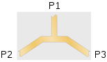
The Tee is the simplest. This is best used for DC and where impedance matching isn’t needed since at the junction of the 3 ports, the impedance is ½ the input impedance.
Adding Resistors
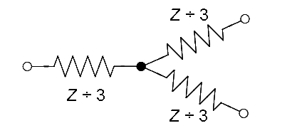
The addition of resistors improves the impedance matching but adds 3 dB of loss, so instead of 50% at each output, it’s only 25%. This added loss also adds some isolation between ports over the Tee.
Improved Design
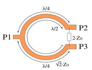
Mr. Ernest Wilkinson improved this with his design by exploiting the properties of quarter wavelengths. The single resistor not only matches the impedance but improves the isolation significantly. This is done by combining signals 180º out of phase. Because it’s based on quarter wavelengths his basic design has limited bandwidth as other designs based on wavelengths.
The design can be modified to have a very wide bandwidth by adding more resistors at the quarter wave points of different frequencies. The loss increases slightly due to the addition of more circuitry.
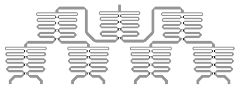
The design is so versatile it can be cascaded.
His design is so versatile that, if wide bandwidth isn’t required, the number of outputs can be even or odd.
Directional couplers (taps)
In general, we call something a splitter if it sends the same amount of signal to every output. However, if a splitter is designed to send unequal amounts of signal, we call that a directional coupler or a tap. The purpose of a tap is to allow for very high signal levels on a long line that serves multiple devices. For example, if you are running signal from the top of a tall building to the bottom, you know you will lose a lot of signal every time you split. So you use a tap instead. In a typical scenario, a tap would send 20dB less signal to one port than another. This will allow devices to get the signal level they expect and not overload. At the same time, a strong signal can go down the line to the next tap.
Diplexers
Another use of splitters is to separate signals that travel along the same line. For example, DISH’s Hopper DVRs receive satellite signal and send network signal over the same wire. A Diplexer is used to separate the signals so the network signal can go to the Joey clients without disturbing the satellite signal.
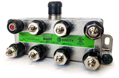
Special cases: DIRECTV SWM and other dual-purpose splitters
DIRECTV uses special splitters for their devices. They are designed to maintain port isolation in the range where satellite signals travel while allowing port-to-port communication in the range where network signals travel. This allows for a very flexible installation. However, because of the low port isolation, these splitters should never be used for anything but DIRECTV signals.
Conclusion
It’s pretty obvious from these diagrams that there’s a lot to the science of splitters, and that really just scratches the surface. Some splitters work with very high bandwidth requirements like satellite. Others will let some frequencies pass from port to port without going back up through the main line. Yet others give maximum isolation between ports.


Be the first to comment on "Get the real story: How does a splitter work?"